
Cycloidal drive generator: a 15:1 worked example
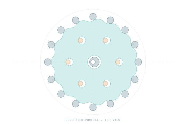
Generate a cycloidal reducer in RatioLab, follow the eccentric motion and export STEP or STL geometry. This free, open-source example uses 16 ring rollers and a 15-lobe disc, with six output pins. Download the complete project to inspect and edit it in the browser or desktop app.
Download the cycloidal project or open the web app.
Open the example
- Download the project JSON using the link above.
- Open RatioLab in your browser, or launch the desktop app.
- In the browser, choose Project → Open project… and select the JSON file. On desktop, use Open project. Save existing work before replacing it.
- Inspect the single-disc assembly. The drawing above shows selected top-view profiles; the downloadable project also contains the generated supporting parts.
Understand the parameters
| Parameter | Example value | What it controls |
|---|---|---|
| Construction | Single disc | One generated cycloidal disc |
| Ring roller count | 16 | The fixed rollers around the disc |
| Disc lobes | 15, derived | One fewer than the ring roller count in this construction |
| Ring roller pitch radius | 40 mm | Radius of the roller centre circle |
| Ring roller radius | 3 mm | Radius of each roller |
| Eccentricity | 1.2 mm | Offset of the disc centre from the input axis |
| Disc thickness | 8 mm | Axial thickness of the disc |
| Output pins | 6 | Pins that transmit disc motion to the output flange |
| Output pin pitch radius | 22 mm | Radius of the output-pin centre circle |
| Input speed | 60 rpm | Prescribed eccentric input speed |
The fixed-ring, eccentric-input construction has an ideal signed ratio of −15:1. A 60 rpm input gives a nominal output of −4 rpm: the output turns more slowly and in the opposite direction about the common shaft axis.
Follow the motion
Play the preview and follow two movements separately: the disc centre follows the eccentric input, while the disc itself rotates slowly. The output pins transmit that slow rotation to the output flange. The disc's orbit is not the output shaft's rotation.
Pause and orbit the view to inspect the disc, ring rollers and output pins. As a first experiment, change only the input speed from 60 rpm to 30 rpm. The ideal ratio remains −15:1, giving −2 rpm output; the geometry does not need to change.
Export STEP or STL
Choose Export and select the available STEP or STL option. Inspect the component selection before saving. Use STEP to continue modelling in CAD and STL when you need triangulated surfaces. Save the project JSON too if you want to return to its parameters later.
The user guide explains export scope and component handling. The browser guide documents browser requirements and limits.
What this example establishes
The preview represents nominal geometry and ideal kinematics. It does not simulate deformation, determine a load rating or establish production clearances. Review the calculation references, motion conventions and model limits when adapting the design.
Compare it with the 4:1 planetary example.